In the world of BIM, accurate data is everything. One of the most critical, yet often overlooked, pieces of data is a project’s georeferencing. How can you be sure that your IFC file truly represents the correct location on Earth? A simple visual check isn’t enough. You need a robust, automated way to audit your model’s coordinates.
For more details check our last blog post about IDS via this link
After some deep investigation, I’ve developed a reliable workflow to ensure IFC files exported from Revit contain the correct georeferencing information and can be automatically validated. This guide will walk you through the entire process, from the crucial export settings in Revit to creating a precise Information Delivery Specification (IDS) file for auditing.

Part 1: The Revit Export – Getting Your Coordinates Right
The foundation of a validatable IFC is a correct export. If the georeferencing data isn’t in the file, you can’t check it. Here’s how to ensure it’s included.
Step 1: Set Your Project’s Real-World Coordinates
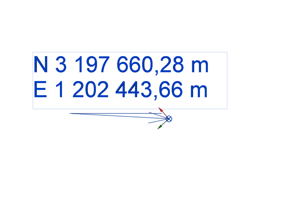
Before anything else, ensure your Revit model is correctly positioned. This means your Project Base Point or Survey Point must be set up with the actual, real-world coordinates for the project site. This is the source of truth for your model’s location.
Step 2: Configure Your IFC Export
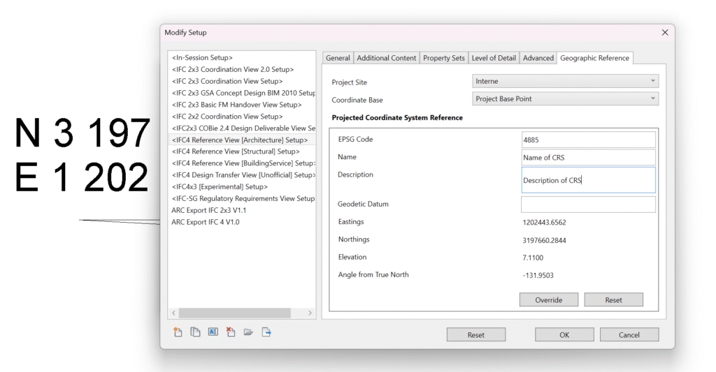
During the IFC export process, don’t just click “Export.” You must dive into the configuration settings. Navigate to the IFC export setup and pay close attention to the “Geographic Reference” tab. This is where the magic happens.
Step 3: Define the Coordinate Base and Projected CRS
You will see two critical options:
- Coordinate Base: Set this to “Project Base Point” (or Survey Point, depending on your project setup). This tells the exporter which origin to use for the georeferencing data.
- Projected Coordinate System (CRS) Reference: This is arguably the most important step. You must input the correct EPSG code for your project’s geographic location. The EPSG code is a unique identifier for a coordinate reference system. An incorrect code will result in an incorrect location.
Part 2: A Quick Sanity Check – Did it Work?
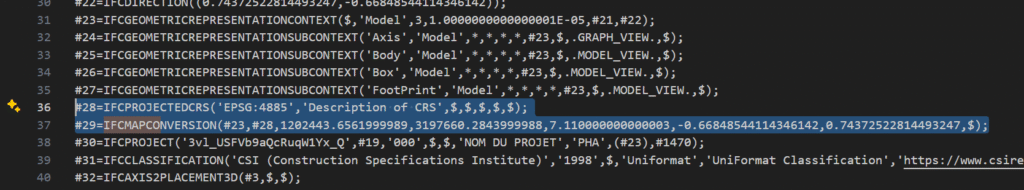
Before building our IDS file, let’s confirm the data exists. An IFC file is just a text file, so you can open it with any text editor (like Notepad++, VS Code, etc.).
Once you have the file open, use the search function (Ctrl+F) and look for these two IFC entities:
IFCMAPCONVERSIONIFCPROJECTEDCRS
If you find entries for both, congratulations! Your georeferencing data has been successfully exported. If not, revisit the steps in Part 1, as something went wrong during the export process.
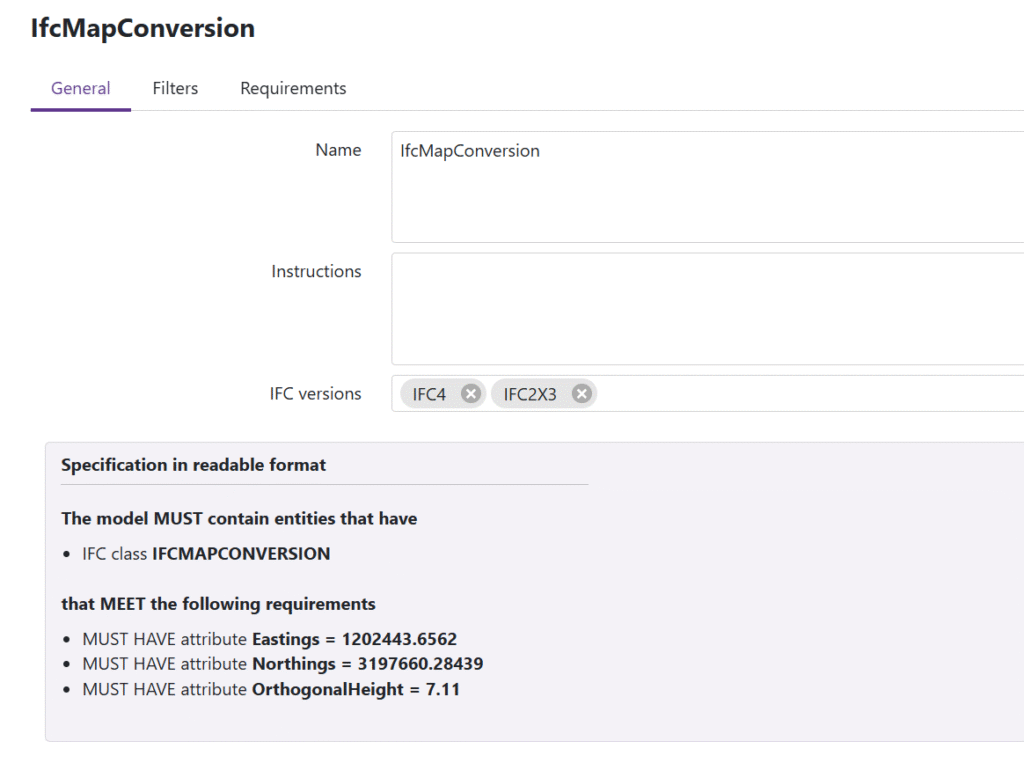
Part 3: Building the Validator – Your Custom IDS File
Now for the automation. An IDS file allows us to define specific requirements that a model must meet. We will create one to check the coordinate values within our IFC. For this task, I used the excellent usBIM.ids editor from ACCA Software, which makes the process intuitive.
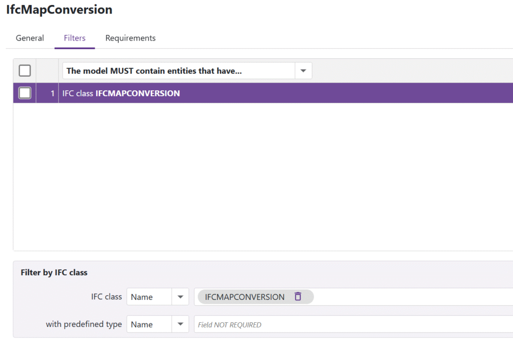
The Logic: Target the Right Entity and its Attributes
The core of our check is to target the IfcMapConversion entity that we verified exists. This entity holds the crucial coordinate attributes. Our IDS specification will apply a requirement to this specific class.
The attributes we need to validate are:
Eastings: The “X” coordinate in the projected system.Northings: The “Y” coordinate in the projected system.OrthogonalHeight: The “Z” coordinate, or elevation.
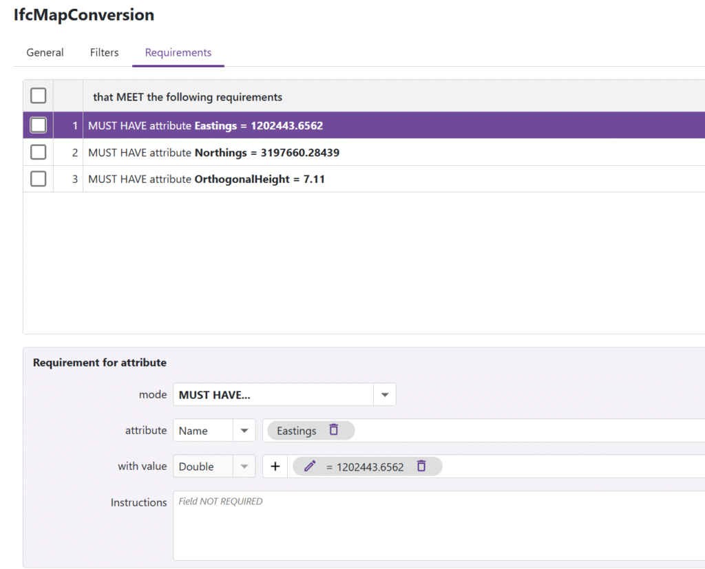
Your IDS requirement will instruct the validation software to find the IfcMapConversion entity and check if the values for these three attributes match what you define.
Part 4: The Moment of Truth – Running the Audit
With our IFC and IDS files ready, it’s time to perform the audit. For this, I use BlenderBIM, a powerful open-source tool that has robust support for IDS validation.
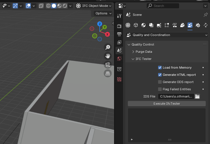
The process is straightforward:
- Open your IFC model in BlenderBIM.
- Go to the IDS validation panel.
- Load your custom IDS file.
- Run the check.
BlenderBIM will then generate an Html report telling you whether the georeferencing coordinates in your model passed or failed the requirements you set in the IDS file.
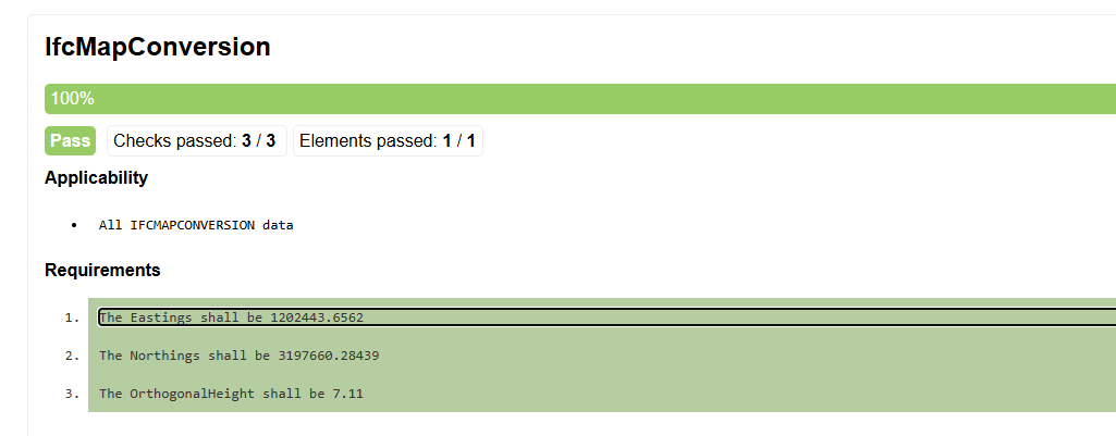
Conclusion: Trust, but Verify with Automation
Ensuring correct georeferencing is fundamental to BIM coordination and data integrity. While it requires careful setup in Revit, the ability to create a simple IDS file transforms the audit process from a manual, error-prone task into a reliable, automated, and repeatable check. By following this workflow, you can be confident that your models are not just digitally correct, but correctly placed in the digital world.
Frequently Asked Questions (FAQ)
What is an EPSG code and why is it so important?
An EPSG code is a unique identifier for a specific coordinate reference system (CRS). Every location on Earth can be described by many different systems. Using the correct EPSG code ensures that your project’s coordinates (e.g., Northing, Easting) are interpreted correctly, placing your model in the exact real-world location. Without it, your coordinates are just numbers without context.
What should I do if I can’t find IfcMapConversion or IfcProjectedCRS in my IFC file?
If these entities are missing, it means the georeferencing data was not exported from Revit. You must go back to the export settings in Revit and ensure you have correctly set the “Coordinate Base” and, most importantly, entered a valid “Projected Coordinate System (CRS) Reference” (the EPSG code). A successful export is entirely dependent on these settings.
Can I use other software for this validation workflow?
Absolutely. The principles are universal. While this guide uses ACCA’s usBIM.ids editor and BlenderBIM, any software that can author IDS files and any IFC viewer that can run IDS validation checks can be used. The key is that the tools must support the buildingSMART IDS standard.